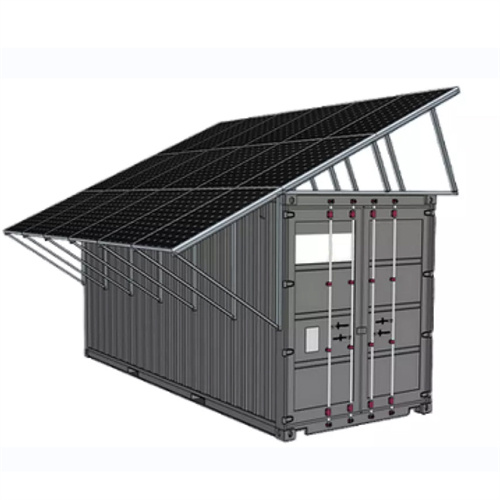
Structure diagram of solid energy storage unit

Large-scale energy storage technology is crucial to maintaining a high-proportion renewable energy power system stability and addressing the energy crisis and environmental problems. Solid gravity energy storage t.
Contact online >>

Flywheel Energy Storage

A review of energy storage types, applications and recent developments. S. Koohi-Fayegh, M.A. Rosen, in Journal of Energy Storage, 2020 2.4 Flywheel energy storage. Flywheel energy storage, also known as kinetic energy storage, is a form of mechanical energy storage that is a suitable to achieve the smooth operation of machines and to provide high power and energy

12.5: The Structure of Ionic Solids

Define the lattice energy of an ionic solid in terms of the energetic properties of its component elements. Make a rough sketch that describes the structure of solid sodium chloride. As can be seen from the diagram, the differences in electronegativity between the elements of Groups 1-2 and those of Group 17 (as well as oxygen in Group 16

Advances in materials and structures of supercapacitors | Ionics

Supercapacitors are a new type of energy storage device between batteries and conventional electrostatic capacitors. Compared with conventional electrostatic capacitors, supercapacitors have outstanding advantages such as high capacity, high power density, high charging/discharging speed, and long cycling life, which make them widely used in many fields

Journal of Energy Storage

However, in most applications, LHTES are required to respond quickly to changes in heat load, but the low thermal conductivity of PCM limits the efficiency of thermal energy storage and release [6].Many techniques have been proposed and applied to improve the thermal performance of the LHTES units, such as the addition of highly thermally conductive porous

Shell-and-Tube Latent Heat Thermal Energy Storage (ST-LHTES)

(b) Multi-tube in shell (single pass): In this type of arrangement, a single shell incorporates multiple tubes with all the tubes having their axis parallel to each other as well as parallel to the axis of the shell gure 13.7a consists of a cylindrical block of PCM with HTF flowing through a set of parallel tubes traversing the block. A single module is shown in Fig. 13.7b.

Current status of thermodynamic electricity storage: Principle

As an efficient energy storage method, thermodynamic electricity storage includes compressed air energy storage (CAES), compressed CO 2 energy storage (CCES) and pumped thermal energy storage (PTES). At present, these three thermodynamic electricity storage technologies have been widely investigated and play an increasingly important role in

Flywheel energy storage systems: A critical review on

The total cost can be broken down into the following categories: (1) ESS cost, which is actually the overnight capital cost of the storage unit and can be divided into two parts, namely cost per unit power output ($/kW) and cost per unit energy stored ($/kWh); (2) power conversion system unit cost which comprises of cost for all equipment

Study on melting characteristics of combined phase change heat storage

Study on melting characteristics of combined phase change heat storage units with different structures based on Entransy theory. Author links open overlay panel Jing Wang a, Wei Li a b c, Solid: 780: 770: 760: Liquid: 900: 860: 860: T m (°C) 45 ± 2: 40 ± 2: 35 ± 2: L (kJ Thermal resistance of heat storage unit represents the energy

Design and experimental investigation of topology-optimized fin

In order to enhance the heat exchange rate between the heat transfer fluid and the phase change material (PCM), the placement of fins in the latent heat thermal energy storage (LHTES) unit is an effective means. To this end, this paper introduces a novel fin structure that can evolve along the optimization process using a topology optimization strategy, aiming to

Reducing power substation outages by using battery energy storage

A battery energy storage system is of three main parts; batteries, inverter-based power conversion system (PCS) and a Control unit called battery management system (BMS). Figure 1 below presents the block diagram structure of BESS. Figure 1 – Main Structure a battery energy storage system

Analysis on the effect of novel topological optimization fin structures

Latent heat energy storage technology (LHEST) is frequently employed to address the temporal and spatial incongruity associated with intermittent renewable energy, especially in solar thermal power systems [1, 2].The phase change accumulator, as the core component of latent heat storage technology, must meet the requirements of excellent thermal

Investigation and optimal design of partially encapsulated metal

The LHTES unit is introduced into traditional building walls to realize passive energy storage buildings and reduce building energy consumption, as shown in Fig. 2. During the daytime, the LHTES unit absorbs and stores solar energy, and releases heat to the building at night when the indoor temperature is low, minimizing building energy

Energy storage

Flywheel energy storage; Solid mass gravitational; Hydraulic accumulator; Pumped-storage hydroelectricity (a.k.a. pumped hydroelectric storage, PHS, or pumped storage hydropower, PSH) They store the most energy per unit volume or mass (energy density) among capacitors. They support up to 10,000 farads/1.2 Volt,

Energy management system for modular-gravity energy storage

Solid-based gravity energy storage (GES) (using unit 3 as an example). (d) Schematic diagram of the slicing of the M-GES power plant. Taking a surface-type M-GES plant as an example, including the improvement based on the MHC proposed in this paper (Considering the power station''s structure, the unit''s capacity, and the system''s

Modelling a packed-bed latent heat thermal energy storage unit

Starting from an initial solid state at point A, the addition of heat to the substance initially results in sensible heating of the solid (A–B) followed by an alteration in crystalline structure (B–C) that results in a solid–solid phase change, further sensible heating of the solid (C–D), a solid–liquid phase change (D–E), sensible

2022 Grid Energy Storage Technology Cost and Performance

Foundational to these efforts is the need to fully understand the current cost structure of energy storage technologies and identify the research and development opportunities that can impact further cost reductions. The two metrics determine the average price that a unit of energy output would need to be sold at to cover all project costs

A review on MoS2 structure, preparation, energy storage

The existing literature offers numerous reviews on the applications of MoS 2 in energy storage [25], [26], [27], there are few systematic comprehensive introductions that are based on the structure and electrochemical properties of MoS 2 this review, we delve into the band structure, crystal structure, as well as micro and nanostructures (such as nanospheres

Handbook on Battery Energy Storage System

3.7se of Energy Storage Systems for Peak Shaving U 32 3.8se of Energy Storage Systems for Load Leveling U 33 3.9ogrid on Jeju Island, Republic of Korea Micr 34 4.1rice Outlook for Various Energy Storage Systems and Technologies P 35 4.2 Magnified Photos of Fires in Cells, Cell Strings, Modules, and Energy Storage Systems 40

Structure diagram of energy storage unit

Islanded AC–DC hybrid microgrids composed of new energy sources, constant power loads and energy storage system are typical non‐linear systems, and guaranteeing large signal stability is

Flexible wearable energy storage devices: Materials, structures,

novel, all ‐ solid ‐ state, flexible " energy fiber " that integrated the functions of photovoltaic conversion and energy storage has been made based on titania nanotube ‐ modified Ti wire

Solid Hydrogen Explained (Again) – Is it the Future of Energy Storage

Working as a storage unit for a fuel cell, metal hydrides have been propelling some German submarines since 2003. 19 As you can imagine, extra weight is a bonus rather than a limitation in this case, as submarines need a lot of counterweight to stay underwater. 20 With a price tag of $500 million, a fuel cell system costs as much as a diesel

Battery energy storage system circuit schematic and main

Download scientific diagram | Battery energy storage system circuit schematic and main components. from publication: A Comprehensive Review of the Integration of Battery Energy Storage Systems

Liquid air energy storage – A critical review

The diagram of research structure. 2. History and functions2.1. indicate that the packed bed filled with solids for cold or heat storage experiences dynamic processes when storing energy. The solid temperature is a function of space and time. energy storage unit, and power generation unit that operate individually in different areas.

Flexible wearable energy storage devices: Materials, structures,

A novel, all-solid-state, flexible "energy fiber" that integrated the functions of photovoltaic conversion and energy storage has been made based on titania nanotube-modified Ti wire and aligned MWCNT sheet as two electrodes. the "energy fiber" could be bent into various forms depending on the application requirement.

Structure diagram of energy storage unit

Structure diagram of energy storage unit. Source publication +14. Large signal stability criterion of AC–DC hybrid microgrids with constant power loads considering reference current limitation.

The structure and control strategies of hybrid solid gravity energy

After obtaining a reasonable system structure, we analyze the control strategies of different structure schemes in detail according to three levels: device, single energy storage

Review on solid-solid phase change materials for thermal energy storage

Inorganic SS-PCMs are able to store/release thermal energy in solid phase using one or combination of energy storage mechanisms including magnetic transformations, crystallographic structure transformations, order– disorder transformations, transformations between amorphous structure and crystal structure. In general, the amount of latent

Structure and components of flywheel energy storage system

Download scientific diagram | Structure and components of flywheel energy storage system (FESS). from publication: Analysis of Standby Losses and Charging Cycles in Flywheel Energy Storage Systems

About Structure diagram of solid energy storage unit

About Structure diagram of solid energy storage unit

Large-scale energy storage technology is crucial to maintaining a high-proportion renewable energy power system stability and addressing the energy crisis and environmental problems. Solid gravity energy storage t.

••A bibliometric study shows SGES technology's evolution a.

AbbreviationsAA-CAES Advanced adiabatic compressed air energy storage BES Battery energy storage CAES Compressed air energy storage CAP-SG.

Energy storage technology can be classified by energy storage form, as shown in Fig. 1, including mechanical energy storage, electrochemical energy storage, chemical energy.

This section uses the bibliometric method to analyze the publications in SGES from a quantitative perspective. It mainly presents the evolution of the publication number, the research hotspot.

There are eight technical routes for SGES: Tower SGES (T-SGES) [8], [9], [10], [11], [12], [13], [14], [15], [16], [17], Shaft SGES (S-SGES) [7], [18], [19], [20], [21], [22], [23], [24], Piston SGE.

As the photovoltaic (PV) industry continues to evolve, advancements in Structure diagram of solid energy storage unit have become critical to optimizing the utilization of renewable energy sources. From innovative battery technologies to intelligent energy management systems, these solutions are transforming the way we store and distribute solar-generated electricity.

When you're looking for the latest and most efficient Structure diagram of solid energy storage unit for your PV project, our website offers a comprehensive selection of cutting-edge products designed to meet your specific requirements. Whether you're a renewable energy developer, utility company, or commercial enterprise looking to reduce your carbon footprint, we have the solutions to help you harness the full potential of solar energy.

By interacting with our online customer service, you'll gain a deep understanding of the various Structure diagram of solid energy storage unit featured in our extensive catalog, such as high-efficiency storage batteries and intelligent energy management systems, and how they work together to provide a stable and reliable power supply for your PV projects.

Related Contents

Contact Integrated Localized Bess Provider

Enter your inquiry details, We will reply you in 24 hours.