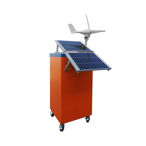
Battery energy storage device schematic diagram


Contact online >>

Battery Control Unit Reference Design for Energy Storage

A battery control unit (BCU) is a controller designed to be installed in the rack to manage racks or single pack energy. The BCU performs the following: • Communicates with the battery system

Schematic diagram of a Battery Energy Storage System (BESS)

The options include transformer reinforcement, adding new cables, installing Photovoltaic (PV) systems, and Battery Energy Storage systems (BESSs). Scenario generation and clustering

Schematic diagram of Li-ion battery energy storage system

Download scientific diagram | Schematic diagram of Li-ion battery energy storage system from publication: Journal of Power Technologies 97 (3) (2017) 220-245 A comparative review of electrical

20.1: Batteries and Simple Circuits

Solution. We start by making a circuit diagram, as in Figure (PageIndex{7}), showing the resistors, the current, (I), the battery and the battery arrow.Note that since this is a closed circuit with only one path, the current through the battery, (I), is the same as the current through the two resistors. Figure (PageIndex{7}): Two resistors connected in series with a

GRID CONNECTED PV SYSTEMS WITH BATTERY

1. The new standard AS/NZS5139 introduces the terms "battery system" and "Battery Energy Storage System (BESS)". Traditionally the term "batteries" describe energy storage devices that produce dc power/energy. However, in recent years some of the energy storage devices available on the market include other integral

What is a battery energy storage system?

Currently, a battery energy storage system (BESS) plays an important role in residential, commercial and industrial, grid energy storage and management. BESS has various high-voltage system structures. Commercial, industrial, and grid BESS contain several racks that each contain packs in a stack. A residential BESS contains one rack.

Reducing power substation outages by using battery energy

A battery energy storage system is of three main parts; batteries, inverter-based power conversion system (PCS) and a Control unit called battery management system (BMS).

Formalized schematic drawing of a battery storage system, power

Download scientific diagram | Formalized schematic drawing of a battery storage system, power system coupling and grid interface components. Keywords highlight technically and economically

Battery Management Systems (BMS)

battery, including: Coulomb counting is a method used by the BMS to estimate the SOC of a battery. It involves measuring the flow of electrical charge into and out of the battery over time. Coulomb counting requires a current sensor to measure the current flowing into or out of the battery, and the BMS calculates the SOC by integrating the

What is a battery energy storage system (BESS) Handbook?

This handbook serves as a guide to the applications, technologies, business models, and regulations that should be considered when evaluating the feasibility of a battery energy storage system (BESS) project.

The Key Components of Battery Energy Storage Systems (BESS)

Battery Energy Storage Systems (BESS) play a fundamental role in energy management, providing solutions for renewable energy integration, grid stability, and peak demand management. In order to effectively run and get the most out of BESS, we must understand its key components and how they impact the system''s efficiency and reliability.

Enphase Energy System planning guide technical brief

Install surge protection devices (SPDs) and residual current devices (RCDs) per local electrical regulations. The following sample Enphase Energy System diagrams help you design your PV and storage systems. PV: 3.68 kW AC. Storage: 5 kWh. Battery breaker 1P, 20 A IQ Battery 5P L1, 1P L1, 1P L1, 1P Consumption CT AC Cable 3 Core (L1, N

Schematic diagram of flywheel energy storage system

Download scientific diagram | Schematic diagram of flywheel energy storage system from publication: Journal of Power Technologies 97 (3) (2017) 220-245 A comparative review of electrical energy

Schematic energy diagram of a lithium ion battery (LIB)

Download scientific diagram | Schematic energy diagram of a lithium ion battery (LIB) comprising graphite, 4 and 5 V cathode materials as well as an ideal thermodynamically stable electrolyte, a

Energy Storage

This is seasonal thermal energy storage. Also, can be referred to as interseasonal thermal energy storage. This type of energy storage stores heat or cold over a long period. When this stores the energy, we can use it when we need it. Application of Seasonal Thermal Energy Storage. Application of Seasonal Thermal Energy Storage systems are

Lithium-Ion Battery

Not only are lithium-ion batteries widely used for consumer electronics and electric vehicles, but they also account for over 80% of the more than 190 gigawatt-hours (GWh) of battery energy storage deployed globally through 2023. However, energy storage for a 100% renewable grid brings in many new challenges that cannot be met by existing battery technologies alone.

Block Diagram Of Battery Management System (BMS)

Earlier limited to heavy and bulky lead-acid storage batteries, large-format batteries were used only where absolutely necessary as a means of energy storage. The above block diagram consists of the battery pack, battery charger, dc-dc converter, air conditioner, etc. BMS or Battery Management System plays a very important role in electric

Battery Energy Storage System (BESS)

This manual deconstructs the BESS into its major components and provides a foundation for calculating the expenses of future BESS initiatives. For example, battery energy storage devices can be used to overcome a number of issues associated with large-scale renewable grid integration. Figure 1 – Schematic of A Utility-Scale Energy Storage System

Comprehensive review of energy storage systems technologies,

Super-capacitor energy storage, battery energy storage, and flywheel energy storage have the advantages of strong climbing ability, flexible power output, fast response speed, and it is combined with other devices [14]. The schematic diagram of FES is presented in Fig. 22. The flywheel is kept on a low pressure state to reduce the

Schematic of battery storage system for solar energy.

Download scientific diagram | Schematic of battery storage system for solar energy. from publication: A Comprehensive Evaluation Model on Optimal Operational Schedules for Battery Energy Storage

Battery schematic diagram

A battery is a device that converts chemical energy into electrical energy. It consists of one or more electrochemical cells, which are connected in series or parallel to increase the voltage or current output. Components of a battery schematic diagram: (BMS) or hybrid energy storage systems. These diagrams include additional components

Batteries as Energy Storage Devices

Batteries Part 1 – As Energy Storage Devices. Batteries are energy storage devices which supply an electric current. Electrical and electronic circuits only work because an electrical current flows around them, and as we have seen previously, an electrical current is the flow of electric charges (Q) around a closed circuit in the form of negatively charged free electrons.

Understanding the Circuit Diagram of a Battery Management

By understanding the circuit diagram, professionals can ensure the proper functioning and longevity of battery packs, contributing to the overall success and sustainability of electric vehicles and energy storage systems. Battery Management System Circuit Diagram. A battery management system (BMS) is an essential component in any battery

How Much Do You Know About Battery Management System Block Diagram

One thing we need to pay attention to is that the specifics of a BMS may vary based on the type of battery technology (e.g., lithium-ion, lead-acid) and the application (e.g., electric vehicles, renewable energy storage). Two Types of BMS Block Diagrams High Voltage BMS Block Diagram:

Flexibility of energy storage devices. a) Schematic diagram of

Download scientific diagram | Flexibility of energy storage devices. a) Schematic diagram of fabricated supercapacitor with PHA gel film and its flexible behavior. Reproduced with permission.[110

Supercapacitor

Schematic illustration of a supercapacitor [1] A diagram that shows a hierarchical classification of supercapacitors and capacitors of related types. A supercapacitor (SC), also called an ultracapacitor, is a high-capacity capacitor, with a capacitance value much higher than solid-state capacitors but with lower voltage limits. It bridges the gap between electrolytic capacitors and

A Guide to Battery Energy Storage System Components

There are many different chemistries of batteries used in energy storage systems. Still, for this guide, we will focus on lithium-based systems, the most rapidly growing and widely deployed type representing over 90% of the market. In more detail, let''s look at the critical components of a battery energy storage system (BESS). Battery System

What role do battery energy storage systems play in transforming energy systems?

Battery energy storage systems have a critical role in transforming energy systems that will be clean, eficient, and sustainable. May this handbook serve as a helpful reference for ADB operations and its developing member countries as we collectively face the daunting task at hand.

Schematics of electrochemical and thermal energy storage devices

Download scientific diagram | Schematics of electrochemical and thermal energy storage devices, showing analogous inputs and outputs a, Electrochemical battery during discharge. b, PCM storage

A schematic diagram of the grid-forming BESS and its device

AC/DC hybrid micro grid system (HMGS) is designed with renewable energy sources (RES) and battery energy storage system (BESS) with unique control schemes, interfaced with multi terminal

Schematic diagram of a typical stationary battery energy storage

Download scientific diagram | Schematic diagram of a typical stationary battery energy storage system (BESS). Greyed-out sub-components and applications are beyond the scope of this work. from

About Battery energy storage device schematic diagram

About Battery energy storage device schematic diagram

As the photovoltaic (PV) industry continues to evolve, advancements in Battery energy storage device schematic diagram have become critical to optimizing the utilization of renewable energy sources. From innovative battery technologies to intelligent energy management systems, these solutions are transforming the way we store and distribute solar-generated electricity.

When you're looking for the latest and most efficient Battery energy storage device schematic diagram for your PV project, our website offers a comprehensive selection of cutting-edge products designed to meet your specific requirements. Whether you're a renewable energy developer, utility company, or commercial enterprise looking to reduce your carbon footprint, we have the solutions to help you harness the full potential of solar energy.

By interacting with our online customer service, you'll gain a deep understanding of the various Battery energy storage device schematic diagram featured in our extensive catalog, such as high-efficiency storage batteries and intelligent energy management systems, and how they work together to provide a stable and reliable power supply for your PV projects.

Related Contents

Contact Integrated Localized Bess Provider

Enter your inquiry details, We will reply you in 24 hours.